In this blog post, we will explore methods for determining the acoustic contributions of various noise sources within a vehicle's cabin. This process, often referred to as decomposition, allows us to break down the overall acoustic environment into individual components attributed to distinct sources.
For instance, when a vehicle is in motion, the internal acoustic environment is typically influenced by road noise and wind noise. In this context, the methods we discuss will help us analyse the impact of both road and wind noise on the cabin's acoustic conditions.
For the sake of simplicity, we will focus on analysing the contributions of a vehicle's HVAC (Heating, Ventilation, and Air Conditioning) system. Our objective is to isolate the noise generated by the HVAC airflow and the noise originating from the HVAC compressor system.
The initial step involves conducting the necessary measurements. To measure HVAC-related noise in the vehicle cabin (including contributions from airflow and the compressor), we position microphones at locations approximating passengers' ear positions. Additionally, we need reference measurements from the sources we wish to decompose. In this case, we place a triaxial accelerometer on the compressor housing to record vibrations caused by the motor system.
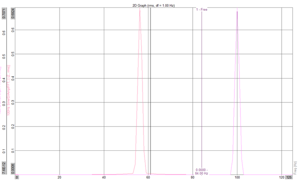
The plot below displays the cabin's acoustic response when the HVAC system operates at maximum RPM. The lower plot provides a visualization of vibrations in the compressor housing along the X, Y, and Z axes.
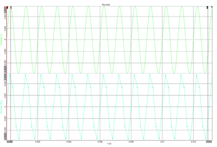
In this example, we aim to separate the contribution of the HVAC compressor noise, leaving the rest attributed to HVAC airflow noise.
An initial step to eliminate contributions from sources other than the compressor is to employ a standard cross-power analysis. This digital signal processing (DSP) function helps identify frequency bins with significant excitation across multiple channels while suppressing those with minimal energy in both signals.
The plot below illustrates the original in-cabin acoustic response alongside the cross-power spectrum of the microphone and accelerometer channels.
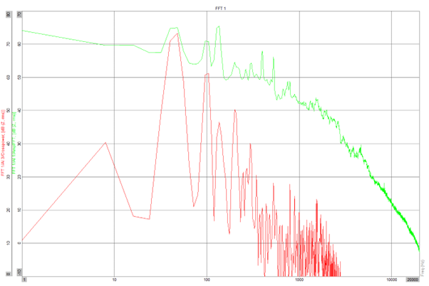
At this point, we start noticing that the motor system predominantly contributes to narrowband peaks, likely associated with motor rotational speed and/or blade pass frequency and harmonics. As expected, high-frequency components in the spectrum are likely due to airflow-generated noise.
A second method we can use to further decompose this data, either independently or in conjunction with the cross-power method, involves a coherence analysis. This method assesses the causal relationship between the source and receiver by evaluating the stability of phase relationships between the signals.
The plot below shows the original cabin acoustic measurements and the coherence analysis between the microphone and the compressor housing accelerometer. The coherence function generates values between 0 and 1, with 0 indicating no causality and 1 indicating complete causality.
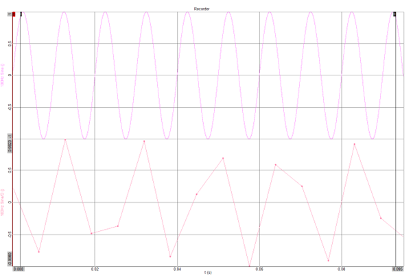
Similar to the cross-power analysis, this method also reveals a clear relationship between the HVAC compressor and peaks in the acoustic response, particularly in the higher frequency ranges.
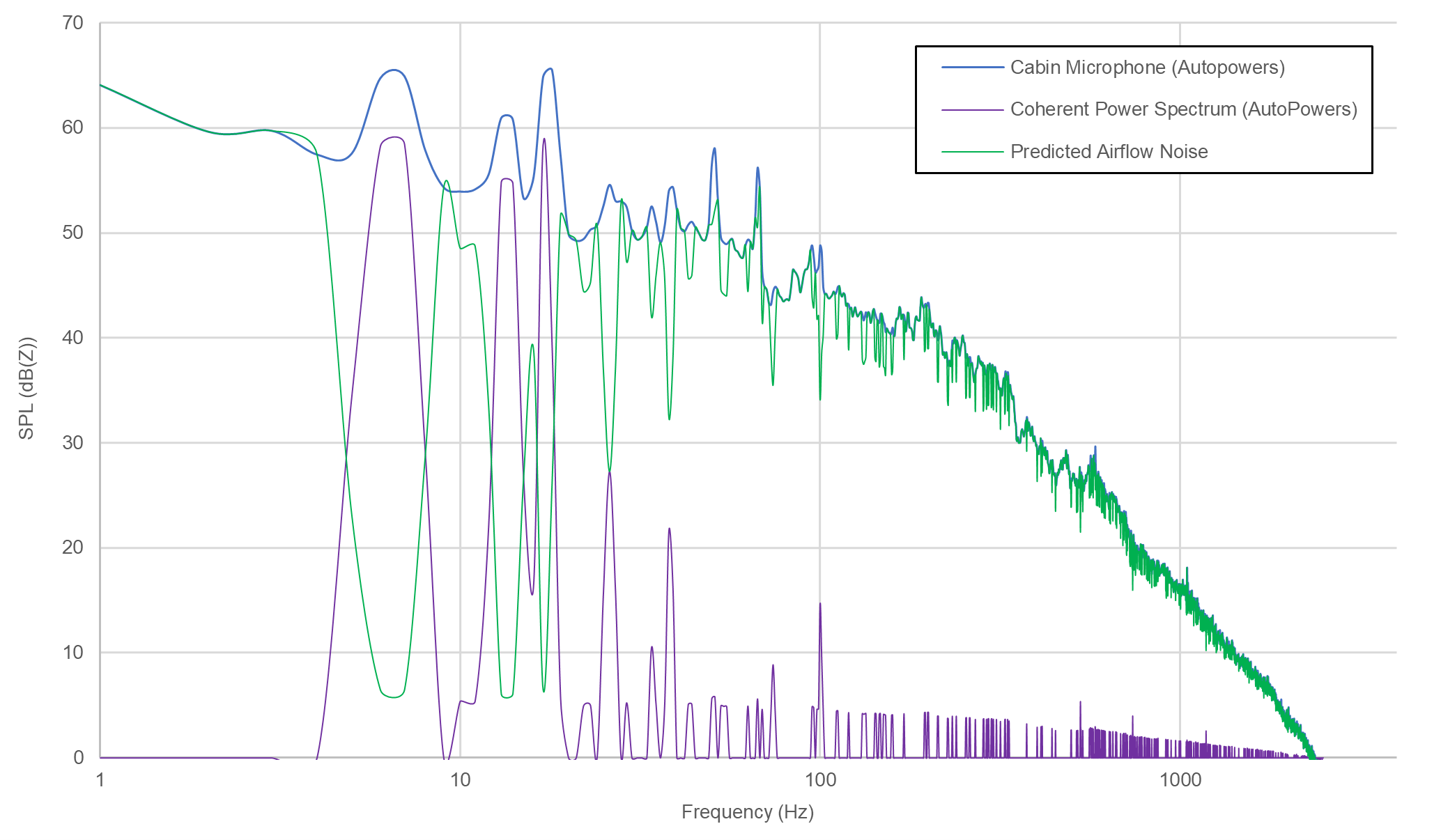
The final step entails calculating the coherent power spectrum of the cabin's acoustic response. This can be applied to either the cross-power output or the original measurement data, as demonstrated in the overlaid plot below.
Finally, by performing a simple subtraction, we can predict the airflow-generated noise. The predicted decomposition between airflow noise and HVAC compressor noise is depicted in the plot below.
PINNED POSTS
No data found
BLOG CATEGORIES
No data found